Archive for the 'Computers' Category

Dell PowerEdge R300 ESM / BMC firmware updates on non-supported operating systems

Dell has generally been quite good about making firmware updates available in a variety of formats. In addition to the normal Windows and Linux versions, most patches are also available as a floppy / USB image or an ISO image (depending on size). Those of us who don’t run one of the operating systems Dell provides support for appreciate them going through the trouble.

However, newer updates for older systems and updates for newer systems seem to no longer provide standalone installers. In theory, Dell provides a quarterly packaged roll-up of all available updates on a pair of DVD images (CDU and SUU). Booting these and wasting about 10 minutes switching discs should get your system updated to the latest versions of all firmware without any additional steps.

Unfortunately, the firmware for the R300’s ESM / BMC has not been on any SUU discs I’ve looked at, and the update is listed as “Critical Security Update” on Dell’s site (look under ESM on the R300’s downloads and drivers page). The only two formats it is available in are “Windows Update Package” and “Linux Update Package”. I figure that’s not a problem, as I can boot a Windows 7 recovery disk and then run the ESM update from a USB drive. Unfortunately, that doesn’t work. You get an error about “unsupported operating system”.

Next, I boot the CDU DVD and select F3 for Advanced Options. This eventually gets me to a Linux shell prompt (CDU/SUU operates under Linux). I mount the USB drive and execute the Linux version of the ESM update. That errors out with “Not compatible with your system configuration” for some unknown reason. Time to investigate further…

Clicking on “Previous Versions” on the Dell page shows the previous version as 2.46 from 2009. Looking at the available formats, one is listed as “Hard-Drive”. Depending on the mood Dell is in when they create the kit, this could be anything from a freestanding binary that writes a floppy image to a drive, to creating an ISO file, or something that just unpacks into a bunch of loose files somewhere, perhaps then trying to run them (incorrectly) on the local system.

I downloaded that file (link here) and discovered it created 3 useful files when it was executed:

  • bmcfl16d.exe – a DOS-based flash utility
  • bmccfg.def – some sort of configuration file
  • bmcflsh.dat – the actual firmware to be flashed

Now all I needed to do was to find newer versions of the last 2 files inside either the Linux or Windows installer. The Linux installer was a pain, and I quickly gave up on it. I had much better luck with the Windows version (link here). Despite being an EXE file, I was able to use WinZip 16.5 to open the file (browse to the directory where you downloaded the Dell update, then make sure you’ve selected “All files (*.*)” in WinZip’s Open Archive dialog). There’s a whole load of un-needed stuff in there (which doesn’t completely explain how a 655KB update turns into a 4800KB Windows binary). Find the bmccfg.def and bmcflsh.dat files and extract them on top of (replacing) the ones from unpacking the older download.

I copied the 3 files onto a bootable USB stick and then used that to boot the R300 to be updated. Here are some screnshots of the various stages of the procedure (it’s very simple – just answer Y or N when asked if you want to perform the update):


If the firmware is already at the latest revision, the utility will tell you that and exit. This can also be used to double-check that the update was successful:

That’s all there is to it. If you want a pre-built .ZIP file with the flash utility and the 2.50 image, I have placed one here for your convenience.

Advanced topics

The bmcfl16d.exe utility has a number of documented and undocumented additional features. You can use the -help option to get a list of the documented features. Before using one of these features when updating a system, be sure you know what you’re doing and have a fallback plan in case the update fails and you’re left with a non-operable system.

There is also an undocumented -advhelp (advanced help) option, which shows the additional undocumented options:

The above caution about knowing what you’re doing and having a fallback plan is doubly important if you try using any of the advanced options.

[Another] New Year, new UPS batteries…

Four years ago, I wrote about replacing the batteries in each of the UPS systems I had here. After nearly 4 years, the batteries were near the end of their useful life, and the week-long power outage after Hurricane Sandy (and the follow-on outages once the power finally came back on) finished them off.

I contacted Batteryspec / Tempest (who I’d used for the last big order, as well as for some smaller orders since then) to get current pricing and shipping info. They were back-ordered on the battery type that the Symmetra uses, and shipping costs (which they have no control over) had increased quite a bit since my last big order.

While I’ve been very pleased with Tempest’s product and service, I figured it couldn’t hurt to shop around, particularly as I was looking at a several-week delay before Tempest had their units back in stock. One of the replies to my original post was from Ken Kostecki, whose company carries the Enersys line of batteries. I decided to send him an email message with the list of batteries I was looking for, asking for pricing and shipping costs. He responded right away and gave me good pricing on the batteries and a much lower freight cost – understandable, since the batteries would be coming from less than 1000 miles away, instead of 3000 miles away. At this weight (1500+ pounds), UPS is out of the question – this type of shipment is normally done with a “Less than truckload” (LTL) shipper. He also confirmed that the date codes on the batteries were recent, and even offered to unpack and charge them for me if I wanted. I said that it wasn’t important as long as the batteries were fresh.

After explaining to Ken that I lived on a narrow side street, didn’t have a loading dock and needed a day’s notice so I’d be home, he confirmed that the shipping quote was still good. [In the past, I’ve had experiences where the shipping company didn’t call first and showed up when nobody was home, then charged a $200 “re-delivery fee” – that can clobber any cost savings that the order started out with. I’ve also had 53′ trailers pull up on the next major street over and tell me to come unload their truck, which didn’t have a lift gate. Carrying 1500 lbs of batteries a block and a half is not my idea of fun. Hence wanting to make sure that everything was all set for curbside delivery.]

Within a few days, the batteries arrived in perfect condition, boxed and wrapped on a pair of pallets. I loaded them into the house and began the process of installing them in the various UPS systems – quite a task, as there were around 160 batteries of various sizes, ranging from the small ones used in the Symmetra to car-battery-sized ones used in the Matrix 5000.

As I replaced the batteries in each UPS, I checked the battery float voltage. Incorrect voltage is the thing that will kill batteries the fastest – if the UPS thinks the batteries need to be “topped up”, it will continuously pump power into the batteries, causing them to overheat and eventually swell and burst. APC units (particularly the smaller ones) seem to drift out of adjustment over time, almost invariably in the direction of overcharging the batteries. The Symmetra and Matrix units were fine. The smaller Smart-UPS units I have (700VA to 3000VA) were all out-of-spec by varying amounts. I had to disassemble a pair of SU1000 units in order to get the batteries out, as they had swelled up so much that they couldn’t be removed without disassembling the battery compartment. I don’t consider this to be a problem with the previous Tempest batteries – it is definitely because the UPS’s cooked them.

I followed the unofficial procedure described here to adjust the float voltage on each UPS to the low side of the acceptable range, since I figure that any future aging will continue to shift toward the high side. After bench-testing each UPS for a few days, I placed them back into service. One of the SU1000’s decided it didn’t want to work properly when hooked up to its load (a Dell mini-tower system). After studying it for some time, I decided I’d be better off simply replacing it, rather than trying to find out what was wrong. Fortunately, there are usually a large number of similar units on eBay, often with a “needs batteries” or “does not include batteries” disclaimer – which was perfect as I had a set of brand new batteries. I located a nice SUA1000 (without batteries) for $85 with free shipping. It had a late 2008 date code, which was perfect – units older than that tend to start developing problems, while newer ones have better charging circuitry but are designed to keep manufacturing costs down. After it arrived, I put the new batteries in it, checked the float voltage, and placed it into service. I now had 8 good UPS systems with new batteries.

One of the things I did was to add 2 more “XR” battery packs to my “life support” UPS. This is the unit that provides power to a pair of electric space heaters (for emergency use only), my stereo / TV, cell phone and other battery chargers, and so forth. It will now power all of that stuff for a little over 2 days (vs. 1 day previously), or even longer if I shut down some of the devices it powers. In the past, I’d never had a power failure lasting more than 24 hours, but the electric utility has proven that they’re woefully unprepared for major disasters.

Back on the subject of the batteries – I’ve been very pleased with the service I received from Ken at Engineered Power Systems – give him a call / email if you’re looking for batteries at a good price with great service:

Ken Kostecki
Engineered Power Systems
St. Louis, MO
877-426-6800
http://www.eps-stl.com

[I’m not posting his email address, in order to keep address-harvesting spambots away – visit his web site for email contact info.]

The GEN II MOD-6_7971

H Carl Ott and Michael Barile recently released the GEN II version of their fabulous MOD-6_7971 Nixie clock, and I ordered several kits from them. The new version adds GPS time synchronization, either via a GPS receiver plugged into the back of the clock, or by using an RF-Link repeater module which talks to the clock over short-range 2.4GHz radio. This clock uses the B-7971 Nixie tube, which displays alphanumeric characters 2½” tall.

The RF-Link lets you completely avoid the problem of needing to position the clock within a few feet of a window or resort to using a bunch of PS/2 extension cords. Now you can put the clock exactly where you want it. The RF-Link remote also includes an indoor temperature sensor and a pushbutton which can be used to remotely turn the clock display on and off.

I have a separate page here describing the clock, but I’m adding a link here so people can find it, and also to facilitate comments (while the actual clock page doesn’t support comments, you can comment here).

Here’s a couple of teaser pictures – click either picture for more info:

MOD-6 Nixie clock

MOD-6 RF-Link

For more info or to order a kit or assembled clock, visit the MOD-6 page at BadNixie.com.

SOPA (and Go Daddy’s FORMER support for it)

Updated 23-Dec-2011 18:30: I received an email response to my letter stating that “Go Daddy is no longer supporting SOPA”. I’ll attach the complete response as the first comment to this post.

There had been a bit of an Internet buzz about SOPA (the Stop Online Piracy Act). Yesterday, Tom’s Guide reported that Go Daddy published a blog entry supporting SOPA. There are a number of sites organizing “boycott Go Daddy” programs and advocating the transfer of domains to other registrars, for example in this post on Reddit and this one on TechCrunch.

As someone who has registered a number of domains with Go Daddy, I wrote them a letter expressing my dissatisfaction with their policy. I’m including it in this blog entry, as I feel that others need to see it as well. Feel free to submit comments (either agreeing or disagreeing with me, but please keep it civil). Hopefully I’ll be able to keep comments open on this post without it degenerating into a free-for-all.

Date: Fri, 23 Dec 2011 00:36:45 -0400 (EDT)
From: Terri Kennedy <TERRY@glaver.org>
Subject: A hopefully more-reasoned SOPA comment from your customer
To: oop@godaddy.com, suggestions@godaddy.com
MIME-version: 1.0

  I read your “Position on SOPA” blog, but since comments are closed there (for obvious reasons), I felt I needed to contact you to tell you my feelings on the subject.

  I’m retired these days, but I’ve been in the computer business since the mid-1970’s. I’ve been an owner or principal of hardware companies, software companies, and ISP’s in the last 40 or so years. There’s no reason for me to mention the names of any of them – some you’ve never heard of, some are quite well known.

  I (and my companies) have suffered economic losses from software piracy (though in those days, we called it “stealing”). So I support REASONABLE anti-piracy measures. However, as currently proposed I feel that SOPA is not a reasonable measure.

  It would force service providers and registrars to act as enforcement agents without requiring the complainant to provide a reasonable justification for the enforcement action. It is essentially a conviction without a trial or defense. Even the much-maligned DMCA provides for the accused to assert a counter claim. Under SOPA, the accused may not even know that they are the subject of an action, until they hear from their customers that their site is inaccessible.

  Under existing legislation, we already have already seen a number of instances where the DMCA was maliciously or inadvertently used to remove or render inaccessible content. In fact, GoDaddy was involved in a recent high-profile instance with vividwildlife.com: http://www.photoattorney.com/?p=3247

  There was also a recent instance where UMG asserted rights to a song, and claim to have a “private arrangement” “outside the DMCA” with YouTube which lets them remove items, thereby stripping away the protections afforded by the DMCA. I am referring to the Megaupload Mega Song, as documented here: http://torrentfreak.com/megaupload-youtube-and-the-dmca-less-mega-song-takedown-111216/

  Further, SOPA appears to be just another escalation in a technological “whack-a-mole” arms race. As John Gilmore famously said, “The Net interprets censorship as damage and routes around it.” In my opinion, this technological warfare accomplishes nothing to prevent illegal acts, especially not ones performed by “commercial” counterfeiting groups and similar organized operations. It just makes life more difficult for the paying customers. Perhaps you’ve seen the “If you are a pirate, this is what you get” image:
http://cdn-www.i-am-bored.com/media/7125_piratemoviechart.jpg

  I would be much happier if you reserved your support for SOPA until it exists in a more balanced and practical form. In your own blog post, you use phrases like “changes we believe are necessary” and “room for some improvement”. As you repeatedly emphasize in your blog, you have over 50 million domains and a full-time presence in Washington. That gives you a very strong position to advocate changes to SOPA which would be more effective while still preserving the rights of the accused.

  I encourage you to reconsider your support of SOPA in its current form, and to work toward modifying it so that it will be both more effective in combating real infringing activities while also greatly reducing the chance that it will be abused.

         Sincerely (your customer),
         Terri Kennedy        http://www.glaver.org
         terry@glaver.org      New York, NY USA

Quantum SuperLoader 3 / L700 / PowerVault 124T Power Supply Replacement

The Quantum SuperLoader 3 is a popular tape backup product for small- to medium-size businesses. It combines 16 tape slots, a tape drive (of varying types and capacity) and an operator panel in a compact, 2RU (3.5″ high) format. I often refer to it as “a triumph of engineering over common sense”, as it uses a Rube Goldberg-esque mechanism (including a wheel that rotates as well as moving up and down, along with 2 independent “conveyor belt” mechanisms), but the large number of these units sold over the years proves it was a successful design. It was also re-branded by a number of companies, for example as the Dell PowerVault 124T, Sun StorageTek C2, HP StorageWorks SSL1016, IBM 1×16 Tape Autoloader, and probably by a number of additional companies.

Unfortunately, many of these devices have been installed for quite some time and are now out of warranty. Parts are beginning to fail more frequently than they would when the units were new. One common failure seems to be a completely dead unit – no lights or fan rotation, and no response to the host on either the SCSI or Ethernet port. This is usually due to a failure of the power supply, not anything more serious. Unfortunately, the Quantum Best Practices for Troubleshooting Superloader3 (PDF) says “Is the unit totally dead, no lights, power or sound? If yes – Replace the loader.” That’s a bit expensive if the unit is out of warranty. Even the IBM version doesn’t show the power supply as a field-replaceable unit.

My first step in diagnosing this dead unit was to open it by removing the cover, which involves removing all of the flat-head Torx screws on the left, right, back, and top as well as an additional 4 round-head Torx screws on the top. Next, I manually ejected the left and right tape magazines (since the unit was dead, there was no other way to eject them). The ejection procedure involves sliding a thin piece of plastic (an old credit card will do, but don’t use one you need as you’ll probably damage the magnetic stripe on it while wiggling it around) vertically between the front panel and the magazine. There’s a small white lever on each side which acts as a catch:

Eject lever - top view

Eject lever - side view

Additional information is available in the Quantum Lodged Tape Removal Instructions (PDF) document. If you cannot eject one of the magazines, it is possible that the magazine drive gear is engaged – refer to the above document for details. In addition to the possibilities listed in that document, it is possible for the loader to have had the power supply fail while in the process of moving a tape from the picker wheel to the magazine – in that case, the magazine can’t be ejected until you remove the loader cover and move the tape fully into the picker (or magazine) by hand.

With the magazines removed, there was more room to work inside the unit. Next, I removed the protective cover between the tape drive and the power supply, unplugged the power supply cables to the rear interface board and the tape drive, and lifted the power supply out of the way. This left the power supply connected to the front panel / loader mechanism. There’s a very tight fit between the loader mechanism and the tape drive and one or the other needs to be removed in order to access this cable. I decided to remove the tape drive (the loader mechanism is connected to the rear interface board by a pair of fragile ribbon cables, so removing the tape drive is easier and safer). There are 4 screws holding the tape drive carrier to the chassis, 2 on the back and 2 on the front between the tape drive and the loader mechanism. The front 2 are somewhat difficult to reach. I suggest using an extension and a magnetic Torx bit for this step. Be aware that at this point the tape drive is still connected to the rear interface board via a SCSI cable and the small library interface cable. You can either unplug these and reconnect them later, or just hold the tape drive to the side while dealing with the power cable on the loader mechanism.

Once I was able to disconnect the old power supply from the loader mechanism, I set the old power supply aside and installed a 4-pin Molex power extension cable on the loader mechanism and reinstalled the tape drive, routing the power cable along the same path as the old one:

Power extension cable

One thing to note in the above picture is the second, unused set of slots in the base pan of the chassis. It appears that some of the possible tape drives that can be fitted are wider than the SDLT600 drive in this unit. If there is no corresponding decrease in the width of the magazine, there may not be enough clearance for the connectors on the type of power extension cable I used. In this case, it would be necessary to use a longer extension cable in order to locate the connectors further toward the back, in the space between the power supply and the tape drive. I used the particular extension cable shown in these photographs because it was the longest one I had on hand, and I didn’t want to make a new, longer one from scratch. Feedback on this issue from users performing the procedure with other drives (particularly LTO models) would be appreciated (use the comment feature).

If you disconnected the SCSI or library interface cables from the tape drive, re-connect them now. Be sure to verify that the cables are located correctly and fully inserted. [I didn’t forget this when working on this loader, but it is a mistake I have made in the past.] If you don’t get both of the cables installed properly, you’ll have to disassemble the whole thing again later to fix it.

Next, I temporarily connected a generic ATX power supply to the rear interface board, tape drive, and the power extension cable for the loader mechanism, in order to confirm that this was a power supply problem:

Test with generic power supply

When I connected the AC power cord to the temporary power supply, the loader immediately commenced its power-up sequence to the point where it complained that no magazines were installed. After installing both magazines, the drive completed its power-up inventory and the loader proceeded to the “System Ready” state, as indicated on the front panel. This confirmed that the only issue was the power supply, and the loader simply needed a replacement of the correct type.

Unfortunately the power supply used in the unit, an Enhance ENP-2316BR, is not available at anything approaching a reasonable price. [As I am writing this, the least expensive one on eBay is $299.95 and the most expensive one there is $795.00. A web search turned up one for $896.00!]

At those prices, it would be less expensive to purchase a whole SuperLoader on eBay (ones with the less-desirable tape formats such as DLT VS160 are currently listed for $299.00 and up) and swap the power supply.

However, I decided to investigate further and discovered that the SuperLoader 3’s power supply is almost a standard FlexATX format unit. The differences are that it has a provision for an external on/off switch and a different quantity and length of power connectors. I initially considered the Enhance ENP-2322B-G as it was made by the same company and shared many characteristics with the original unit. Unfortunately, this series was discontinued by Enhance in June 2011, and any searches for it turn up “replacement” units, not all of which would be physically compatible with the original (mostly relocating the fan and/or changing the location of the mounting screws). I settled on the Sparkle Power FSP200-50PLB (which is not shown on their web site, and the 250 Watt version is labeled “Discontinued soon”), as it had the same fan location, etc. as the original unit. The only issue is that the replacement power supplies do not have cabling for the rear panel on/off switch. However, the loader has an on/off button on the front panel and the rear switch is equivalent to unplugging the power cord. Rather than opening up the replacement power supply, voiding the warranty, and installing switch wires, I decided to leave the rear power switch disconnected and non-functional. This power supply cost $44.99, including shipping – quite a substantial savings from the “best” price of $299.95 for the original supply.

Here are some comparison photos of the old (left or top) and new (right or bottom) power supplies:

Power supplies - top view

Power supplies - end view

Power supplies and cables

As you can see in the last picture, the new supply has more cables and most are longer (though one is shorter) than on the old supply. That’s why I installed the extension cable on the loader mechanism – I knew the cable on the new power supply wouldn’t reach all the way.

I proceeded to request an eject of the right side magazine via the front panel and then powered down the loader via the front panel pushbutton. The front panel will not respond to any commands other than the power button when either magazine is removed. This makes it impossible to remove the second magazine as the loader insists on having the first magazine re-inserted. After powering down, I performed the manual eject procedure on the left side magazine.

Next, I installed the new power supply, connected all of the cables and neatly tied the excess into a bundle between the power supply and the tape drive. There are several things to note about this step. First is that the bundle of cables should be as low as possible, in order to not obstruct the air vents on the upper rear of the the tape drive. Next is the routing of the power cable to the extension cord installed previously. Use one of the far end connectors from the power supply, not one in the middle of the cable. Ensure that the cable is securely held in the provided tabs – if it comes loose it will interfere with the cycling of tapes in the right-hand magazine. Last is the use of cable ties. Do not use rubber bands or anything besides cable ties. Things are packed quite tightly inside the unit and if a rubber band or similar breaks and starts floating around inside there it could cause serious damage. Once everything was properly placed and tied down, I reinstalled the protective cover / air shroud over the power supply:

New power supply with cables tied

Cover reinstalled

Extension cord connected

At this point I reinstalled the magazines (checking for clearance where the extension cord connects to the power supply cord) and verified proper clearance of the power supply in the rear panel:

Everything installed - rear view

Note that the new power supply has a 115/230 Volt selection switch, while the original did not (it auto-detected the voltage). If the power supply you use has a selection switch, make sure it is set to the proper position for the power you have (in the US, normally the 115V setting, though some datacenters use 230V for efficiency purposes).

Lastly, I powered up the unit and verified that it completed its inventory and proceeded to the “System Ready” state. Once that was completed, I powered the unit down via the front panel and reinstalled the cover. After powering back up, the loader is ready and should hopefully provide many additional years of serivice:

All done - System Ready

Here are a few additional notes that may be useful if you perform this procedure:

Most FlexATX power supplies of 200 Watts or higher should be electrically compatible with the loader’s requirements. It is important to confirm physical compatibility as well. The main issues will be the location of the power connector and fan opening – some supplies exchange their positions which would lead to a partially-obstructed cooling fan; having a 20-pin ATX connector (some supplies have only the 20-pin, some have a 20-pin and a separate 4-pin, and some have a 24-pin – the first two will work, the last won’t); having a hole for a mounting screw above the power connector location; and having the proper bracket on the cable side of the power supply (if a supply doesn’t have that bracket, you may be able to re-use the one from the original supply, but confirm that there are at least mounting holes for the bracket on the new power supply).

If you get the urge to clean the dust out of the loader while you have it open, be very careful, particularly if you are using a compressed-gas duster. NEVER use compressed gas to spin a fan’s blades – if you must clean a fan, hold the blade so it does not rotate while you use the compressed gas. Also, NEVER used compressed gas on warm electronics. This is particularly important with DLT drives – if you do this on a DLT8000-family drive (for example), you WILL destroy at least one of the tape spool motors from thermal shock. Let the unit cool down, overnight if possible, before dusting.

Dell PERC 3/DC / MegaRAID Elite 1600 Battery Replacement

Updated 6-Apr-2012: BatteryPrice no longer lists the HF-C1U battery. Please refer to my comment at the end of this post for more information.

The Dell PERC 3/DC RAID controller (a re-branded MegaRAID Elite 1600) was a very popular RAID controller on older server systems. Here is a picture of the Dell version:
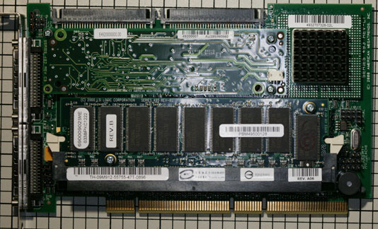
PERC 3/DC board

This controller was available with two different battery backup options – the normal “Battery Backup Unit” (BBU), and a “Transportable BBU” which was mounted on the back of a custom memory module. For some reason, Dell PERC 3/DC cards have both the regular BBU and the transportable one installed, but the battery is only installed on the transportable BBU. All of the 50 or so of these controllers that I’ve seen have both installed. The battery on the memory module gives new meaning to the term “Battery Backed RAM”:
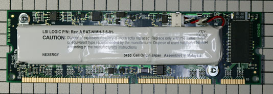
Battery Backed RAM module

Unfortunately, these batteries are well past their useful service life. They no longer hold a charge and many have started to leak. Take a look at the bottom center of the white plastic wrapper in this picture:
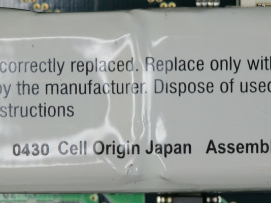
Leaking Battery

Several years ago, I contacted LSI Logic (who purchased the MegaRAID product line from AMI a long time ago). Unfortunately, they could no longer provide the battery module as it was an obsolete part. At the time, I was able to salvage batteries from my spare controllers (or so I thought – more on this in a bit) and use them on my production boards.

Recently, I had a number of systems start reporting “Charge failed” or “Battery pack missing” for their battery status. So I began investigating replacement batteries again.

I contacted the original manufacturer (Nexergy) as well as a number of custom battery pack manufacturers. Unfortunately, all of the ones that replied stated that they could not produce the battery pack. Nexergy said “This is an obsolete part and the cell you have as well as the tooling to make the pack is no longer available to us.

The only references I could find on the Web, searching for the part numbers on the battery – 4920100000 or BAT-NIMH-3.6-01 – were from other people looking for replacement batteries, or from companies wanting to sell used controllers (which would also have bad batteries on them).

Therefore, I decided that if I wanted to have working battery backup packs, I would need to make replacements myself. My first step was to remove the battery from the memory module and un-wrap the outer whiite plastic casing:
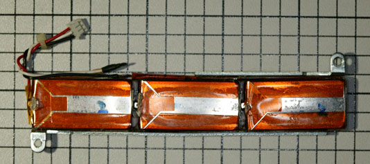
Inside of battery pack

As I had suspected, there was a lot of corrosion where the chemicals had leaked out of the battery:

Corroded batteries

Fortunately, I was able to determine that the actual batteries inside the module were of a standard size, known as a HF-C1U (PDF spec sheet here). That meant that I could purchase replacement cells and assemble a new module by re-using the existing brackets and wiring harness.

The HF-C1U battery is becoming difficult to find, as it is nearly obsolete. I located a large quantity at a company called BatteryPrice. They also offered the batteries with an option to have solder tabs installed on the batteries. It is important to get batteries with this option, as the normal variety without the tabs will be impossible to solder. I placed an order for batteries and they arrived in two days:
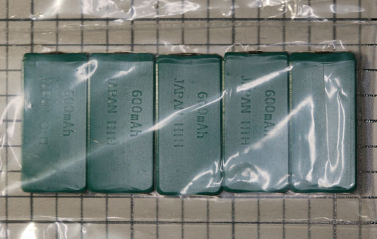
Bag of replacement batteries

If you decide to perform this repair yourself, I suggest you order additional batteries as you may damage some when soldering them.

I soldered three of the batteries together, with the positive terminal of one to the negative terminal of the next one. It is important to have the correct polarity. One end of the battery will be a solid metal plate – that’s the negative end. The positive end will have a small metal button on a mostly-plastic plate. Here’s a view of the positive end, with the solder tabs bent up to provide clarity:
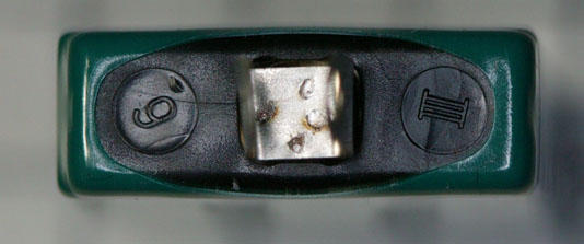
Positive end of battery

Next, I used clear plastic shipping tape to hold the 3 new batteries together, by wrapping each of the 2 connections with tape:
Batteries taped together

Here is a comparison of the old string of batteries and my new set:
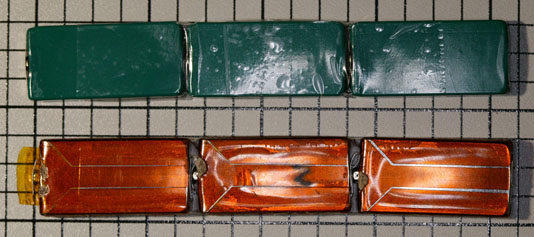
Old vs. new batteries

Next, I carefully removed the cable and strap from the old battery pack. The red wire was unsoldered, which let me lift up the whole assembly from the string of batteries. The strap is spot-welded to the end of the old batteries, so I peeled it back and carefully cut it off to leave as much of the strap as I could, for soldering onto the new batteries:
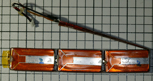
Lead on batteries

Lead removed from old batteries

In addition to the wires and the strap, there is a thermistor (thermal sensor) which the controller uses to limit the charge rate of the battery. Here is a close-up view – the thermistor is the angled piece connected to the white and black wires:
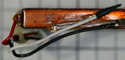
Thermistor

After removing the old cable and strap assembly, I soldered it onto the new string of batteries. The red wire connects to the positive terminal, and the end of the strap connects to the negative terminal at the other end of the new string. I then used more clear plastic shipping tape to mount the two metal brackets and to hold the thermistor close to the side of the battery pack:
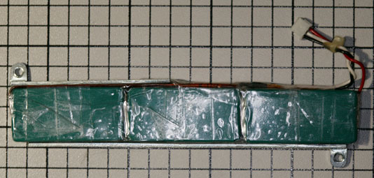
New batteries all wired

Here is a comparison of the old and new batteries. It is important to correctly position the brackets so that the spacing between the holes is the same as on the old battery, and that the brackets are aligned with the back edge of the batteries so there is no gap between the brackets and the circuit board when installed:
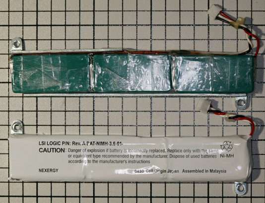
Old vs. new batteries

The next step is to enclose the completed battery pack in an insulating material. The original wrapper was unusable, as I had to cut it in order to remove it. I decided on a combination of electrical tape and heat shrink tubing. A complete wrap with electrical tape would probably work as well, but wouldn’t look as nice.

The first step is to use electrical tape to cover both ends of the battery pack, since the heat shrink tubing will leave that area exposed:
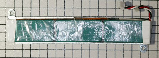
Ends taped

Next, I cut a piece of 3/4″ diameter heat shrink tubing (3M part number 5174-1345, available from Mouser Electronics). The tubing is slightly longer than the battery pack. We will rely on this in order to shrink the ends:
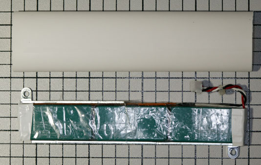
Next to heat shrink tubing

I cut a small notch in one end of the tubing to accomodate the power cables and slid the battery pack into the tubing:
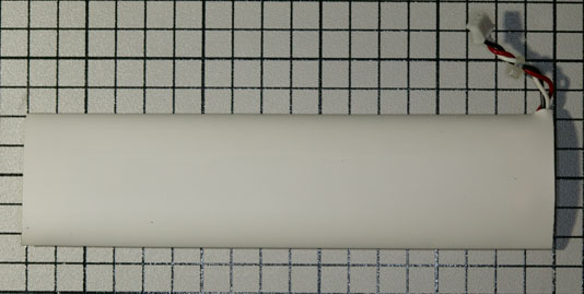
In heat shrink tubing

Next, I used a heat gun (a hair dryer would also work) to start shrinking the tubing onto the battery pack. It is important to go slowly to avoid overheating the batteries, which could damage them:
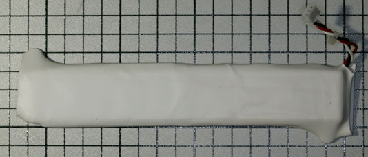
Partially shrunk tubing

I used a razor blade to carefully remove a small piece of the tubing where it was pulled against each mounting tab:
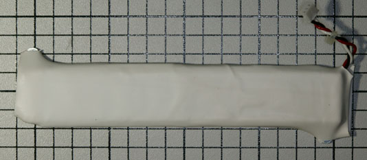
Tabs trimmed

Here is a close-up of the tubing cut at the tab:
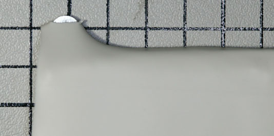
Close-up of trimmed tab

I then used the heat gun to complete the shrinking of the tubing, which fully exposed the tabs:
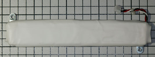
Tabs exposed

In the previous picture you can see the extra heat shrink tubing on both ends of the battery. The next step is to trim that down to a reasonable amount:
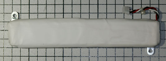
Excess tubing trimmed

Now we’re finally ready to mount the battery on the memory module. Because the heat shrink tubing is a bit thicker than the original wrapper, we need to add some spacers between the circuit board and the battery at each of the two screw locations. The best bet would be some nylon spacers, but I only had metal ones. If you use metal ones, make sure they’re small enough to not short out any of the wiring on the circuit board. I also made up a label with the part number and date of assembly:
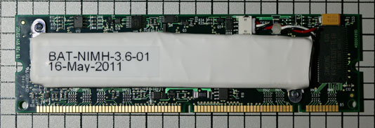
Battery installed on module

I went ahead and made a number of additional battery packs so I could get them charged before replacing the bad batteries in my systems:
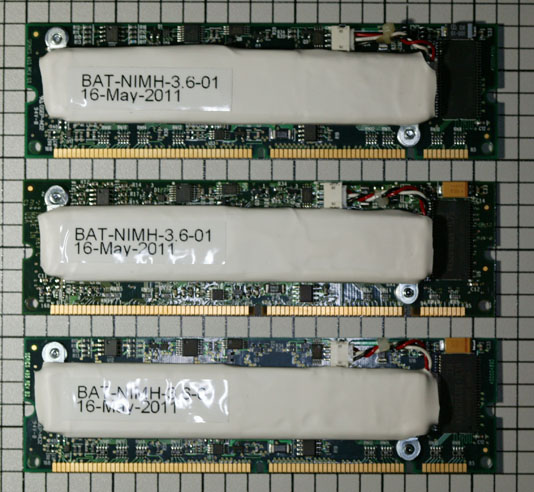
3 completed batteries

The batteries are shipped in a partially-charged state, normally about .8 volts compared to the labeled 1.2 volts. I made a simple power adapter using two pieces of solid CAT 5 wire, so I wouldn’t have to poke around on the memory module itself:
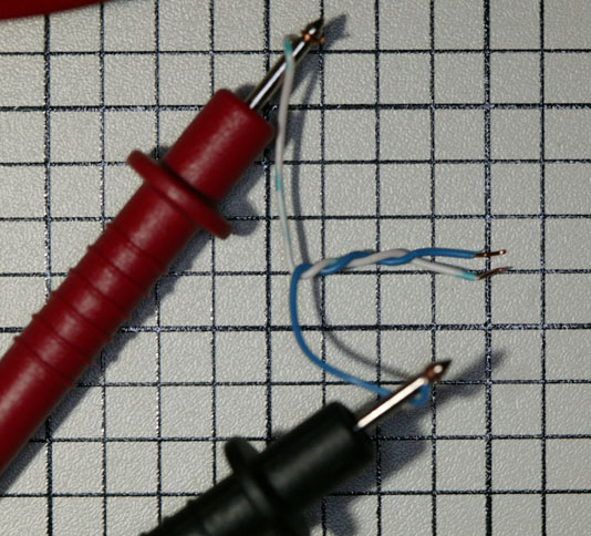
Test adapter

Here is how the adapter is used:
Adapter and battery

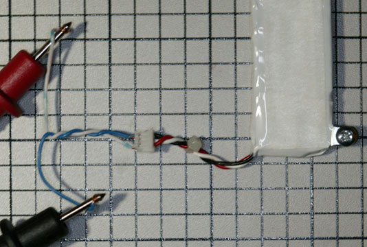
This is the reading from one of the dead original battery packs, showing a voltage of approximately 0.4 volts. This battery has been discharged beyond recovery and can never be recharged:
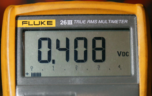
Dead battery

It is important to note that the system this battery was used in (both the controller BIOS menu and the operating system) thought this was a perfectly good battery, despite it being completely dead. With only the positive and negative wires and a temperature sensor, the controller can’t really tell what the state of the battery is without trying to use it. This controller doesn’t have the capability of scheduled or on-demand battery tests – that came later with the 3Ware controllers.

In fact, I never found the BIOS display to say anything other than that it is completely happy with a battery:
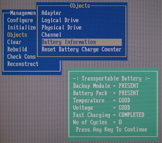
BIOS battery menu

Once I booted the operating system (FreeBSD, in this case) I was able to see more useful data. Each amrstat command was issued about a half hour apart, showing the pack as charging and eventually done:
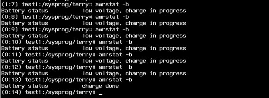
amrstat report

It is probably a good idea to go into the controller’s BIOS setup menu and reset the charge count to zero:
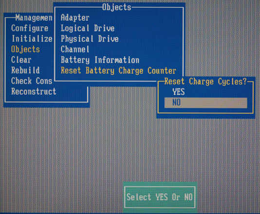
Reset charge count

After letting the battery charge for 12 hours, I removed it and measured the voltage again. The reading of around 4.1 volts is the expected value for a just-charged 3.6 volt battery pack. It will decrease over time, and when it falls below a certain value, the controller will begin charging again:
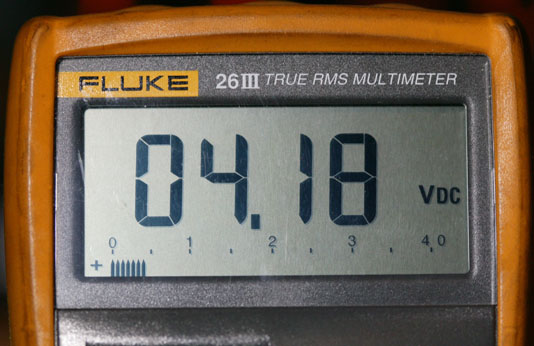
Voltage of new battery

APC Symmetra RM Front Panel Battery Replacement

I am in the process of restarting an APC Symmetra RM UPS that has been in storage, powered off, for several years. After I installed new batteries in the SYBT2 modules (I had removed them before storing the unit – see my earlier post) – and pro-actively replacing all the fans – see this post, I powered the unit on.

Unfortunately, I was greeted with this rather ominous message:

Panel showing failure message

I didn’t know what “–Failed— Fail!” meant, but it didn’t sound good. Scrolling around in the menus, I discovered that the message was apparently coming from the date/time settings:

Date/time failure message

Both the date and the time were displaying the “Failed” messages and it was not possible to edit either field, the way the date and time is normally set. After swapping out various parts including both Intelligence Modules and the Power Module, I decided to try swapping the front panel with one from a different Symmetra unit. The other front panel displayed the date and time properly, leading me to the conclusion that the problem was in the front panel display module, not the Symmetra itself.

I tried using the front panel “Copy” function on the good front panel to copy all of its settings to the UPS, then swapped back to the bad front panel and did a copy operation to copy from the UPS to the bad front panel. That didn’t solve the problem, so it was time to investigate further.

There are three screws on the back of the cover panel which includes the display panel and the APC logo. Two of them directly hold the display module, while one holds the APC medallion (which needs to be removed to remove the front panel):

Three mounting screws on back

At that point, it was a simple matter to remove the four screws at each corner which keep the two halves of the front panel housing joined, and I removed the front panel circuit board (actually a stack of two boards, one for the display and another with the circuitry):

View of circuit boards

The brownish-yellow rectangular component in the middle of the board is a TIMEKEEPER® SNAPHAT® battery module. This device was designed to “piggyback” on top of a special integrated circuit package, so the battery could be replaced if needed. There are a number of other devices on the market where the battery is not removable, so this is a convenient feature. Here is a close-up of the battery module:

Close-up of battery module

It was a simple matter to carefully remove the battery module, revealing the integrated circuit underneath:

Close-up of socket on IC

I then installed the new battery, and plugged the panel back in to see what it would display. Fortunately, no further work was needed as it immediately showed the default date and time:

Panel is now working

I reassembled the front panel, installed it back in the Symmetra, and set the date and time:

Panel re-installed in Symmetra

It looks like everything is now working perfectly on that Symmetra, and it was much less expensive than purchasing another front panel (the least expensive used one I could find was around $250), as well as keeping components out of the e-waste stream. The replacement battery cost around $5, plus shipping.

If you perform this repair, or even if you just take a close look at your Symmetra front panel, you will want to make sure you’re running the latest firmware for the front panel. APC calls this “Rackmount PowerView” on their web site, and the latest version is 14. The number like .001 after the 14 is the language version (for example, 1 is English and 5 is Spanish). In order to update the panel firmware you’ll need the rather odd Y-cable that came with your Symmetra – it adds a 9-pin serial connector in between the front panel and the intelligence module. Full instructions are on the APC web site.

The Ultimate Studio 1558

Updated March 4th, 2021 to reflect current hardware. You might want to look at my post “The Dell Studio 1558 – Still a nice laptop in 2021” for a more recent perspective, or see a list of all of my Studio 1558 articles here.

A number of people have asked me what changes I made to my 1558 to describe it as “one killer system” (in a comment replying to a poster in the antenna entry). Here’s what I can think of, off the top of my head:

  • Upgrade CPU from Core i5-450M to Core i7-740QM
  • Upgrade memory from 6GB to 16GB (system limit)
  • Upgrade display from glossy 720p to matte 1080p
  • Upgrade keyboard to backlit model
  • Upgrade DVD burner to Blu-ray burner (UJ-235A)
  • Replace lid with one that has all the antennas in “brushed silver” (previously I had a lid which matched the color of my race car, but over the years the matte surface got sticky)
  • Replace palmrest with one that has a topo map pattern instead of the default chainlink (which also includes a new touchpad)
  • Upgrade wireless LAN card to Intel Ultimate-N 6300
  • Install Bluetooth 365 module
  • Install DW5808 mobile broadband / GPS card
  • Replace 320GB HD with 1TB Samsung 860 EVO SSD
  • Upgrade battery from 6-cell to 9-cell (aftermarket as Dell no longer sells replacement batteries for the 1558)
  • Make the power supply more sleek – replace the “hammerhead” power cord with a normal one and remove the rubber strap (I use Velcro cable ties to manage all of my cables)
  • Install Windows 10 LTSC x64 instead of Windows 7 Home Premium x64
  • Use a nice Targus “Unofficial” 16″ slipcase to carry the system

As configured, it gets a Windows 7 Experience Index of 5.7 (yuck!), but that’s due to a poor desktop graphics score from the Mobility Radeon HD 5470. [Of course, the integrated graphics option would probably be a lot worse – if you have a score for that, let me know in the comments.]

Dell Studio 155x 1080p Screen Upgrade

As promised, here’s the article on upgrading your Studio 155x from a 720p screen to a 1080p one.

First, I should caution you that I did this on a Studio 1558 with the ATI Radeon HD 5470 graphics option and a 720p LED panel. I can’t promise that it will work on models other than the 1558, or with the older ATI HD 4750 or built-in Intel graphics. If you have success with any of those, comment here and I’ll add that information.

Some people might ask why I didn’t purchase my 1558 with the 1080p screen in the first place. By the time I was ready to buy the laptop, Dell had cut way back on the available configurations as they were phasing out the Studio line. Also, if you look at used / refurbished 155x systems on eBay, you’ll see that most of them have the 720p screen and that 1080p units cost more (and have less selection) than purchasing a 720p unit and upgrading the screen yourself.

Refer to the service manual (or DCSE if you have it) for detailed disassembly procedures. With some practice, you can do this without dismounting the lid from the base, but for first-timers I’d recommend following the service procedures.

If you have a lid without the wireless broadband or Bluetooth antennas (see earlier post), this would be a good time to change lids since you’re going to have the system apart anyway. A spare bezel (interchangeable parts W440J or 06DV9) may be useful to have, in case you break any of the latch tabs when removing the old one.

Assuming your 1558 has discrete Radeon HD5470 graphics, you will need a W805M cable. Refer to the parts list at the end of this article if your 1558 has integrated graphics. This connects the mainboard to the flat panel, and also includes the cable for the camera. You cannot re-use the W439J cable from your 720p display – it has different wiring. If you purchase a used cable, you will also need some double-sided tape to attach the cable to your new panel. Be careful when purchasing this cable – many eBay sellers think these 2 part numbers are interchangeable – they aren’t. To help you identify a cable in an eBay listing (watch out for “Picture may not be of the actual item” in the description), here are extreme close-up photos of the 2 cables.

This is the W439J cable for a 720p display (LED panel end). Note that there’s a big gap in the middle of the connector with no wires, and a sequence of blue and black (some look white due to the camera flash) wires to the right of the gap:
W439J (720p) cable

This is the W805M cable for a 1080p display (LED panel end). This cable has wires spaced pretty evenly throughout the connector. The sequence of yellow and blue wires indicates that this is for a 1080p panel:
W805M (1080p) cable

You will also need either a H162K (gloss) or C088T (semi-matte) 1080p LED panel. Watch out for “compatible” panels – these 2 part numbers have a display ID (EDID) coded into them, and the notebook won’t accept the display panel if this ID is missing. If purchasing on eBay, you might want to ask the seller for a photograph of the back of the panel, and/or a guarantee of a 100% refund if the panel isn’t compatible.

Here is what the back of the C088T panel looks like:
Back of the 1080p panel

This is a close-up of the label with the Dell part number:
Dell part number sticker

The first thing I suggest doing is plugging your new cable into the new panel and running a few tests. Do NOT stick the tape on the cable to the panel yet. You can lean the new panel up against the lid (in front of the old panel) and plug the cable into the mainboard.

Your first test will be to run a panel power-up diagnostic. To do this, press and hold the “D” key on the keyboard (D for display) while pressing the power button. The display should cycle through a series of solid colors and then go dark. With this test, you’re verifying that you have the cable attached properly and that there are no bad pixels (or an acceptable number, if you purchased a panel with possible pixel defects to save money). A brief flicker before the panel displays the first solid color (white) is normal and not a defect with the panel.

If that test passes, power off the system and then power it back on. You should see the Dell logo and the system should then boot into Windows (or whatever operating system you are running). If you get a black screen and the system appears dead, you have a panel that does not have its EDID programmed (most likely), an incompatible panel, or you have a system that doesn’t support 1080p (not likely, at least if you have the same 1558 with HD 5470 graphics that I do).

At this point, you can shut down the system and commence the panel swap. Set your new panel aside while you remove the old panel from the lid. Be sure to carefully unplug the cable from the camera before pulling the old panel away from the lid. Set the old panel face-down on a padded surface (to prevent scratching it). Place your new panel on the padded surface in the same orientation. You should now see where the sticky tape holds the cable to the old panel (3 places – by the panel’s 40-pin connector, at the edge of the panel where the cable changes to round, and at the edge of the panel where the camera is located). Carefully peel the backing off the new cable’s sticky tape and stick it to the new panel. This will involve pressing (gently!) on two areas of the panel that have “Don’t Touch!” warnings.

Now, remove the mounting brackets from the left and right sides of the old panel (2 screws on each side) and transfer them to the new panel. Left and right are NOT interchangeable, so keep track of what goes where. If you are building a whole new lid, you could use a set of spare brackets, part number W981J. You may need 4 screws to go with the brackets if they aren’t included. You might also want the camera, part number 7RGXF. With all of those parts, you can build a whole new lid and keep the original as a spare.

Carefully re-install the new panel, taking care to plug the webcam cable in before trying to seat the panel all the way. Re-attach the lid to the base of the PC if you removed it. Plug the display and camera cables into the mainboard and boot your operating system to ensure functionality. Be sure to test the webcam as well as the display – you don’t want to have to disassemble the lid once you put the bezel back on. Make sure that the display cable is routed under the tab at the point where it makes a 90-degree turn toward the connector. If the cable isn’t properly located, you’ll get a bulge in the keyboard surround because it won’t seat properly. I’ve observed this on new systems from Dell as well.

If the display and camera are operating correctly, you can now attach the bezel to the lid and replace any other parts that you removed to work on the lid, such as the keyboard surround.

You may find that the default Windows text size is too small when using a 15.6″ 1920 x 1080 display. You can refer to this Microsoft article to select a larger text size. Dell ships their 1080p 155x systems with this set to 125%. Dell also modifies the login screen font size, which requires editing the Windows Registry. You can find an article describing the procedure in Microsoft Answers.

Here are the most common part numbers you will need:

  • 4DKNR – 1558 motherboard with discrete Radeon HD5470 graphics
  • G939P – 1558 motherboard with integrated CPU graphics (no quad-core support, often doesn’t have WWAN connector)
  • 2X6C1 – heatsink/fan assembly for discrete Radeon HD5470 graphics
  • 644D0 – Heatsink for integrated CPU graphics
  • W956J – Fan for integrated CPU graphics
  • W805M – display cable for discrete (1920 x 1080 display only)
  • W439J – display cable for discrete (all except 1920 x 1080 display)
  • NHKMC – display cable for integrated (1920 x 1080 display only)
  • RWH6V – display cable for integrated (all except 1920 x 1080 display)

Converting a system from integrated graphics to discrete Radeon HD5470 graphics will require a 4DKNR motherboard, a 2X6C1 heatsink/fan assembly, and a W805M or W439J display cable, depending on your screen resolution.

Edit: Updated 24-Mar-2021 to fix dead link to Dell service manual and add a section on motherboard and display cable part numbers and upgrading from integrated to discrete graphics.

APC Symmetra RM Fan Replacement

Two years ago I wrote about the second set of replacement batteries for my APC Symmetra RM UPS. Those batteries are still working, but at 8+ years old the various fans in the UPS were getting a bit tired and making various high-pitched whines and grating noises, so it was time for a complete set of replacement fans.

There are 3 different types of fans used in the Symmetra RM – ones in the SYPM2KU power module (2 fans each), ones in the SYTF2 transformer (2 fans each – see footnote), and one in the Symmetra RM chassis itself.

The fans used in the power module are Mechatronics F8025X24B-FHR which is rather hard to find. I purchased mine from Online Components. You will have to splice the connectors from the old fans onto the wires of the replacement fans. If your UPS has sufficient redundancy to allow removal of one power module at a time, you can replace these fans without shutting down the UPS.

The fans used in the transformer are NMB-MAT 3115PS-12T-B30. These are widely available and I purchased mine from Newark Electronics. Note that it is perfectly normal for only one of the two fans to run – the other one is used only when the transformer detects an overheating condition. The cable for these fans just plugs into the fan – no re-wiring is necessary. You will have to shut down the UPS and disconnect the transformer to work on the fans, however.

The main Symmetra RM fan is a Comair-Rotron FE12H0X-039453 which is a semi-custom part for APC. This fan also has a sensor to report its speed, so you can’t just substitute a random 80mm fan. Fortunately, APC makes it possible to order this part at a reasonable price. It is APC part 490-0024B. I ordered mine from CDW, and despite it being a special-order item, it shipped rapidly. This fan comes with the necessary connector pre-installed. It can be replaced while the UPS is running, however the UPS MUST be placed into bypass mode via the switch on the rear panel, or the UPS will shut down with a “System fan fault” error when you unplug the old fan.

The old fans provided nearly 9 years of continuous service, and not all needed replacing – I just decided it would be better to replace them all at once rather than one-at-a-time as they became noisy.